
Abstract
This version is written for engineers, product managers, and integration teams evaluating the opticalCON® HYBRID MED platform as a design-in interconnect. The paper focuses on the connector topology, optical and electrical performance, mechanical envelope, cleaning behavior, and the available qualification data reported in the Neutrik source pack. It does not function as a regulatory submission or a substitute for OEM-level verification.
Engineering note: The source documents use both product-level and subassembly-level specifications. Where temperature, environmental, or cable-construction values differ, this paper keeps them tied to the specific assembly rather than forcing a single number onto the whole platform.
1. Scope and document basis
This paper consolidates the technical content in the supplied opticalCON® HYBRID MED brochure, application sheet, chassis and cable datasheets, breakout-cable datasheet, cleaning instruction, and NTP14 technical paper. The focus is the interconnect itself: channel architecture, interface construction, optical budget, electrical limits, mechanical performance, and qualification evidence.
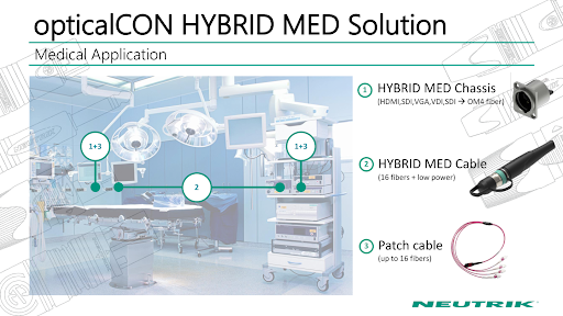
The product is presented as a hybrid medical fiber-optic connection system that combines up to 16 optical channels with two low-power electrical contacts in one ruggedized, push-pull, D-shape interface. The chassis acts as a feedthrough with rear MPO patch access, while the cable-side assembly uses a lensed PRIZM® MT optical interface and a hybrid cable with power conductors integrated into the same cable body.
2. Functional topology and interface architecture
At system level, the platform is a coordinated set of three assemblies: (1) a front-mounted female chassis connector, (2) a pre-assembled hybrid cable assembly, and (3) breakout or patch components that transition the optical lanes to downstream equipment. That matters because the architecture is not just a plug; it is a service and integration concept.
2.1 Chassis-side architecture
The NO16FD-XP chassis connector is specified as a female feedthrough receptacle with one rear MPO socket, two crimp power contacts, and one shell ground contact for the cable shield. Neutrik states that the panel cut-out matches the company’s approved D-shape format, which lowers integration friction for OEMs already using D-size connector footprints.
2.2 Cable-side architecture
The cable-side assembly uses a ruggedized hybrid plug with a lensed 16-channel ferrule, two AWG 16 power paths, a push-pull locking system, and an anti-kink boot. The application sheet highlights ‘no open surfaces,’ dirt protection, a glove-compatible release geometry, and a color-coded / easy-ratchet opening scheme intended to simplify repeated handling in clinical settings.
2.3 Breakout and signal fan-out
On the optical side, the source pack shows breakout options of 4x LC, 6x LC, 8x LC, and 16x LC. The application sheet explicitly associates 4x LC with 4K and 6x LC with 5K / 8K use cases. The breakout assembly uses lensed MTP® to LC transition hardware and Corning ClearCurve® OM4 cable, which means the HYBRID MED interface can be inserted upstream of more conventional optical fan-out topologies rather than forcing the full system to stay proprietary end-to-end.
2.4 Consolidated platform architecture
|
Assembly |
Primary elements |
Published part / family |
Technical role |
|
Front panel / receptacle |
Female chassis connector, rear MPO feedthrough, 2 power contacts, shell ground |
NO16FD-XP |
Panel interface and serviceable pass-through |
|
Cable plug |
Lensed ferrule, push-pull lock, anti-kink boot, hybrid optical + power cable |
NKO16M-XP-0-* family |
Primary mating connector and cable assembly |
|
Optical fan-out |
4x / 6x / 8x / 16x LC breakout with lensed MTP® transition |
NKOB16M*-XP-0-* family |
Maps optical lanes to downstream equipment |
|
Rear patching |
MPO patch connection on rear of chassis |
System-level integration element |
Allows replacement and service without rewiring front panel |
3. Optical subsystem
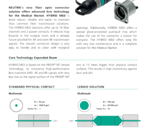
The technical differentiator in HYBRID MED is the lensed PRIZM® MT optical interface. Neutrik contrasts it against a standard physical-contact multimode surface and states that the signal surface of the PRIZM® MT lens is 13 times larger than the physical-contact surface. In engineering terms, the system is moving away from direct-contact dependence and toward an expanded-beam style interface with higher tolerance to particulate contamination and handling wear.
Published optical values in the brochure and breakout-cable datasheet are consistent: insertion loss is specified as typical 0.65 dB per connection and maximum 0.90 dB per connection, with return loss typical 28 dB and minimum 25 dB. The platform is specified for multimode OM4 operation at 850 nm and 1300 nm.
One technical wrinkle worth preserving: the cable datasheet lists a cable construction with 24 fibers, while the marketed interface is described as supporting up to 16 fiber channels. That is not necessarily a contradiction, but it does mean the cable-construction datasheet and the active-channel marketing summary are not identical views of the same design. OEM teams should therefore confirm lane allocation at the assembly level when defining breakouts, spare fibers, and optical budgets.
|
Parameter |
Published value |
Engineering implication |
|
Optical interface |
PRIZM® MT lensed / expanded-beam style |
Improves contamination tolerance versus physical-contact systems |
|
Active fiber channels |
Up to 16 |
Supports dense multi-lane routing |
|
Cable construction |
24 fibers listed in cable datasheet |
Requires lane-allocation confirmation during design-in |
|
Fiber type |
Multimode OM4, 50/125 μm |
Compatible with high-bandwidth short-reach medical imaging links |
|
Wavelengths |
850 nm / 1300 nm |
Standard multimode transmission windows |
|
Insertion loss |
Typ. 0.65 dB, max. 0.90 dB per connection |
Connection budget must be included with downstream MPO / LC losses |
|
Return loss |
Typ. 28 dB, min. 25 dB |
Supports stable multimode transmission within published use envelope |
4. Electrical, mechanical, and cable construction data
HYBRID MED is not an optical-only product. The hybrid architecture includes two low-power contacts, which is where the platform starts to differentiate from pure fiber medical connectors. The brochure states a maximum wire size of 16 AWG, maximum rated current of 10 A, rated voltage of 12 V AC at 50 Hz, and contact resistance below 7 mΩ. The brochure also lists transfer resistance to ground below 10 mΩ, insulation resistance above 10 GΩ, and insulation resistance after damp heat above 1 GΩ.
Mechanical published values are similarly direct: insertion force and withdrawal force are both below 45 N, locking force is above 900 N, and the typical mating-life rating is 10,000 cycles. The technical paper adds more substance by measuring contact resistance before and after lifetime cycling and by reporting cable retention, impact, and flexing performance.
At cable level, the standalone hybrid cable datasheet specifies a 9.5 mm overall cable diameter, TPE-U jacket, 700 N maximum tensile load in both static installation and dynamic operation, minimum bend radius of 95 mm static and 145 mm dynamic, and crush resistance of 500 N/dm. Four conductors are listed, along with a 0.61 mm² conductor value and storage / installation temperature ranges specific to the cable construction.
|
Domain |
Parameter |
Published value |
Source context / note |
|---|---|---|---|
|
Electrical |
Power contacts |
2 contacts; max 16 AWG; max 10 A; 12 V AC @ 50 Hz |
Brochure and chassis datasheet |
|
Electrical |
Contact resistance |
< 7 mΩ; technical paper average 1.8 mΩ initial, 4.7 mΩ after 10k cycles |
Brochure + NTP14 |
|
Mechanical |
Mating forces |
Insertion < 45 N; withdrawal < 45 N; locking > 900 N |
Brochure / chassis datasheet |
|
Mechanical |
Lifetime |
10,000 mating cycles |
Brochure, chassis, breakout, NTP14 |
|
Cable |
Construction |
24 fibers, OM4, 4 conductors, 9.5 mm OD |
Cable datasheet |
|
Cable |
Routing limits |
700 N tensile; 95 mm static bend radius; 145 mm dynamic bend radius |
Cable datasheet |
|
Breakout |
Jacket / fire behavior |
FRNC; IEC 60332-1-2; IEC 60332-3-22 Cat.A; IEC 60754-1 / -2 |
Breakout-cable datasheet |
5. Environmental performance, cleaning, and maintainability
The source pack presents environmental values by subassembly. The brochure lists product-level operation from 0 °C to +40 °C and storage from -20 °C to +60 °C. The chassis datasheet lists -40 °C to +75 °C, while the breakout-cable datasheet lists -10 °C to +70 °C and the cable datasheet lists storage from -40 °C to +70 °C with installation from -5 °C to +50 °C. The right engineering read is simple: qualify the full assembly to the narrowest condition that applies to the actual finished configuration.
Cleaning and contamination control are central to the product’s value proposition. The cleaning instruction states that small contamination should be removed using dust remover / canned air. For heavier contamination, Neutrik specifies a dry cleaner for PRIZM* MTP* endfaces (P/N 1689). The instruction explicitly warns users to disconnect both cable ends before cleaning and not to look into the beam.
NTP14 extends that maintenance story with a long-term cleaning-resistance test. Three connectors were cleaned five times per day for 100 days using Orosept VK Concentrate, Aquasonic 100, and Kleen Ultra Glas Cleaner. The paper reports no wear or damage after 500 cleaning intervals per chemical. That is not the same thing as a blanket compatibility statement for every disinfectant in a hospital, but it is meaningful evidence that the connector was not treated like a delicate showroom part.
|
Item |
Published data |
Technical interpretation |
|
Cleaning instruction |
Air for light dust; dry cleaner P/N 1689 for heavier contamination |
Routine field cleaning is designed into the maintenance flow |
|
Cleaning resistance test |
5 cleanings / day x 100 days x 3 chemicals; no wear or damage reported |
Connector appears tolerant to repeated cleaning with tested agents |
|
Chassis design |
Rear MPO feedthrough; easy repair and replacement |
Service events can be isolated without fully rebuilding the front-panel interface |
6. Qualification evidence from NTP14
The technical paper is where the product stops sounding like a brochure and starts behaving like an engineered interconnect. The tests are framed against IEC 61753-1 main groups, with specific procedures referenced for temperature change, retention, impact, flexing, durability, contact resistance, dielectric strength, insulation resistance, and cleaning resistance.
|
Test |
Conditions |
Reported result |
Why it matters |
|
Change of temperature |
IEC 61300-2-22; 72 h; -25 °C to +70 °C; 850 nm, 5 m cable |
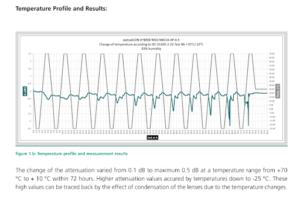
Attenuation change 0.1 to max 0.5 dB from +70 °C to +10 °C; higher loss at -25 °C attributed to condensation |
Shows optical sensitivity under cycling and highlights condensation management |
|
Cable retention |
IEC 61300-2-4 tension test |
Approved for min. 500 N and 60 s readjustment without adverse effects |
Supports strain-relief credibility under handling loads |
|
Impact |
IEC 61300-2-12 Method A; 5 drops; 1.0-1.9 m; 25 mm steel plate |
No critical damage; full function after tested drops |
Addresses accidental drop exposure |
|
Flexing |
IEC 61300-2-44 + 3-4; 20,000 cycles; 10 N; ±90° |
Attenuation change < 0.30 dB; no visible cable damage |
Important for repeated routing and repositioning |
|
Mating durability |
IEC 61300-2-2 + IEC 60512-2; 10,000 cycles |
Insertion loss remained < 0.9 dB; return loss > 25 dB; locking remained functional |
Confirms life-cycle stability |
|
Contact resistance |
IEC 60512-2 test 2a |
Average 1.8 mΩ initial; 4.7 mΩ after 10,000 cycles |
Electrical path remains within published limits after wear |
|
Dielectric strength |
IEC 60512-2 test 4a; unmated contact-to-housing |
2.3 kVAC measured / conditional > 2.3 kVAC |
Supports electrical isolation performance |
|
Insulation resistance |
IEC 60512-2 test 3a; 500 V DC |
Results reported within defined range; meter max 100 GΩ |
Confirms insulation performance under test setup |
7. OEM integration considerations
The connector should be treated as infrastructure, not as a commodity line item. That means the design review should cover optical loss budget, electrical power budget, panel real estate, cable routing, cleaning workflow, and service strategy as one package.
7.1 Optical budgeting
A conservative connection budget should start from the maximum published insertion loss of 0.90 dB per HYBRID MED connection, then add the losses of any rear MPO patching, LC fan-out, and equipment-side optics. The source pack sells the platform on low loss, which is fair, but real systems do not get a free pass on budget arithmetic just because the brochure uses nicer adjectives.
7.2 Power-path limits
The two electrical contacts are best read as auxiliary low-power delivery rather than a substitute for primary equipment power. The published 12 V AC / 10 A rating is meaningful, but it is not a blank check for every downstream device category. Current draw, voltage drop, duty cycle, connector heating, and regulatory constraints still need to be closed at OEM level.
7.3 Environmental envelope management
Because the brochure, chassis, breakout, and cable datasheets publish different temperature ranges, the finished device should be validated to the narrowest envelope of the installed stack-up. This is especially important when the same platform is used in one product as a panel feedthrough and in another as a mobile or frequently cleaned cable set.
7.4 Cleaning and condensation control
The temperature-cycling result in NTP14 is a useful engineering warning: low-temperature attenuation increase was attributed to condensation on the lenses. That is not a deal-breaker, but it does mean cold storage, room re-entry, and cleaning / drying procedures should be written into service SOPs rather than left to wishful thinking.
7.5 Serviceability
The rear MPO feedthrough architecture and front-replaceable chassis concept are practical advantages. A service event can be isolated to a connector or patch component instead of forcing invasive rewiring. In equipment with tight uptime targets, that design choice can be worth more than a modest delta in connector cost.
8. Technical comparison with opticalCON QUAD MED
QUAD MED and HYBRID MED are not interchangeable design choices. QUAD MED uses a physical-contact optical system with four data channels and no integrated power. HYBRID MED moves to a lensed interface, expands channel count to sixteen, and adds low-power contacts. The tradeoff is that QUAD MED publishes a lower per-connection loss in the comparison sheet, while HYBRID MED brings more lanes, more functional consolidation, and a maintenance story built around lensed optics.
|
Attribute |
QUAD MED |
HYBRID MED |
Technical reading |
|
Optical interface |
Physical contact |
Lensed contact / PRIZM® MT |
HYBRID MED prioritizes contamination tolerance |
|
Function set |
Data only |
Data + low power |
HYBRID MED reduces cable count |
|
Fiber count |
4 channels |
16 channels |
HYBRID MED supports denser imaging / routing use cases |
|
Comparison-sheet loss |
< 0.4 dB / connection |
Typ. 0.65 dB / connection |
QUAD MED is lower loss on the comparison sheet |
|
Cleaning tools |
IBC cleaning stick |
Dust remover / dry cleaner |
Maintenance workflows differ |
|
Lifetime |
5,000 mating cycles |
10,000 mating cycles |
HYBRID MED publishes longer mating life |
9. Conclusion
opticalCON® HYBRID MED is technically interesting for the right reasons. The platform combines a lensed multichannel optical interface, two integrated power contacts, a robust push-pull mechanical format, and a service-friendly chassis feedthrough architecture. More importantly, the supplied technical paper backs up the story with meaningful IEC-referenced data for temperature cycling, retention, impact, flexing, durability, contact resistance, dielectric strength, insulation resistance, and cleaning resistance.
For engineering teams building high-bandwidth indoor healthcare systems, the main decision is not whether the connector looks sophisticated. It plainly does. The real decision is whether the system benefits from fiber + power consolidation, contamination-tolerant optics, and serviceable front-panel architecture enough to justify design-in. Where that answer is yes, HYBRID MED is not just a nicer connector. It is the right class of connector.
Where the answer is no, forcing it into a simple data-only link would be like hauling hay with a racehorse: impressive, expensive, and missing the point.
References
[1] NEUTRIK opticalCON HYBRID MED brochure, NF27 V4 202010.
[2] opticalCON HYBRID MED Application sheet.
[3] opticalCON HYBRID MED chassis datasheet (NO16FD-XP).
[4] opticalCON HYBRID MED cable datasheet (NDS20).
[5] opticalCON HYBRID MED breakout-cable datasheet.
[6] opticalCON HYBRID MED Cleaning Instruction, BDA 598 V2.
[7] NTP14 – opticalCON HYBRID MED Technical Paper.
[8] opticalCON QUAD MED cable sheet, used only for direct comparison points shown in the application sheet.
